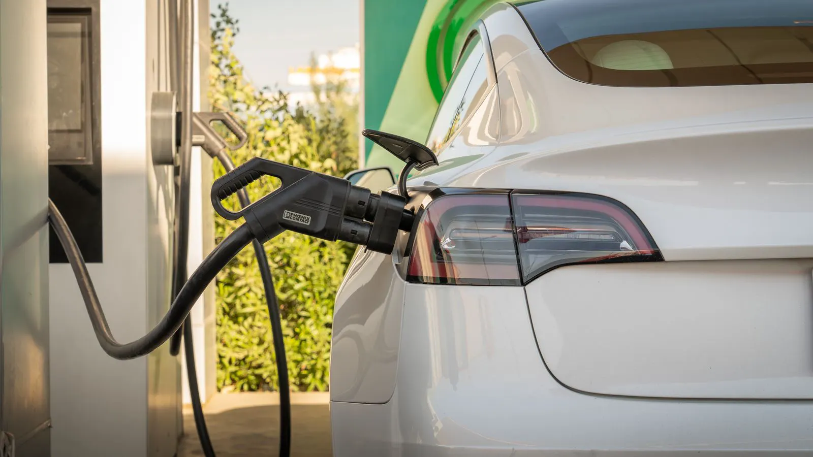
CCS1 suits North American fleets while CCS2 serves European and most global markets. The choice depends on your vehicle fleet, charger hardware, and grid connection standards. Verify local utility requirements before ordering hardware.
- CCS1 uses a single combined plug for AC and DC power, primarily in North America.
- CCS2 uses separate AC and DC ports on one housing, common in Europe and Asia.
- Vehicle fleet compatibility dictates the physical connector choice for your site.
- Local utility regulations may influence charger power levels and grid connections.
- Check cable length and service requirements when sourcing hardware.
What defines the physical difference between these connectors?
The Combined Charging System, or CCS, is the standard DC fast charging interface used by most major automakers. The “1” and “2” refer to the pin configuration and the AC charging port integrated into the same housing.
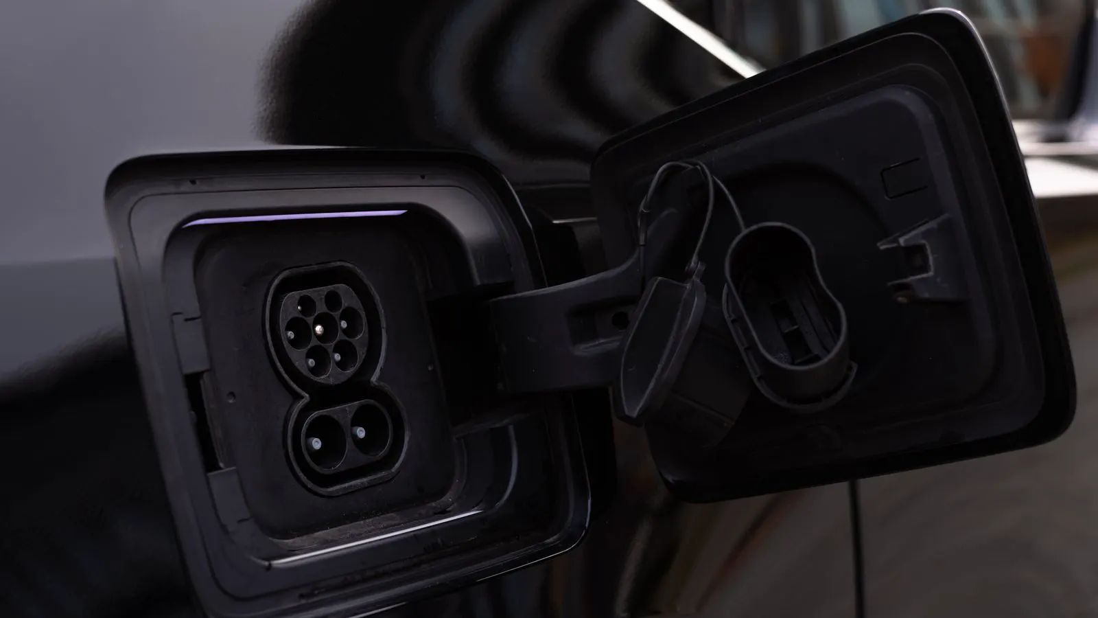
CCS1, known as the Combined Charging System, places the AC Type 2 port above the DC pins. The DC pins sit in a single, unified connector. This design is the standard in North America. It allows a single cable to handle both AC and DC charging. The physical layout creates a distinct profile where the AC socket sits vertically above the DC contact points. This specific arrangement simplifies cable routing for North American facilities because the AC and DC functions share one physical entry point into the vehicle.
CCS2, also called the Combined Charging System, places the AC Type 2 port to the side of the DC pins. The AC and DC connections remain physically separate within the same housing. This is the standard across Europe, much of Asia, and other regions. In this design, the AC socket is positioned horizontally next to the DC port. The separation allows for independent mating actions in some service scenarios, although the cables remain distinct. The housing shape is wider than the CCS1 variant to accommodate the side-by-side arrangement.
The physical shape matters for service. A CCS1 cable will not fit a CCS2 port, and vice versa. Mixing them up causes downtime. The pin layout also affects how the connector mates with the vehicle. Engineers must verify the mating tolerance and the locking mechanism. A slight misalignment can damage the pins or the housing. The weight of the connector also varies. A heavier connector requires a stronger suspension arm or a longer cable to manage the load. These physical differences are not cosmetic. They dictate the hardware selection for the entire charging station.
How does vehicle fleet compatibility drive the sourcing decision?
The vehicle determines the connector. You cannot change a vehicle’s charging port. You must match the charger to the fleet you serve.
If your site serves US-based fleets, CCS1 is the standard. Most US OEMs equip their vehicles with this interface. Sourcing a CCS2 charger for a US site means you need an adapter, which adds cost and complexity. Adapters introduce an additional point of failure. They also add length to the cable run, which can affect the charge rate due to voltage drop. For a high-volume fleet, even a small voltage drop across an adapter can reduce the efficiency of the DC fast charging session.
For European or international fleets, CCS2 is the norm. Most European OEMs use this standard. Sourcing a CCS1 charger here requires the same workaround. The adapter approach is rarely cost-effective for a permanent installation. If the fleet is mixed, the site must accommodate both interfaces. This often means purchasing two separate charging units or a multi-port unit that supports both standards.
Check your vehicle list before ordering. Ask for the charging port type from the fleet operator. A mixed fleet may require two separate chargers. Do not rely on the vehicle model name alone. Some model variants have different charging ports depending on the market. Always verify the physical port on the specific unit you intend to deploy.
Which standards apply in each region?
CCS1 follows the J1772 standard for AC and the SAE J1772 DC fast charging standard. CCS2 follows the Type 2 standard for AC and the IEC 62692-2 for DC.
These standards define the pin count, voltage levels, and communication protocols. They ensure the charger and vehicle can talk to each other safely. The communication protocol is as important as the physical pins. The charger and vehicle exchange information about power capability, temperature, and fault status. If the protocols do not match, the charging session will not start, or the vehicle will limit the charge rate.
In North America, J1772 is the governing standard. In Europe, IEC 62692 is the reference. When sourcing, ask the vendor which standard their hardware meets. Some chargers support both, but the physical port is still one or the other. The internal electronics may be capable of handling both protocols, but the external interface is fixed. Verify the standard compliance certificate from the vendor. This document confirms that the hardware meets the required safety and performance specifications.
How do cable lengths and service requirements change the choice?
Cable management is part of the physical interface. CCS1 uses a single cable that contains both AC and DC conductors. CCS2 uses two separate cables, one for AC and one for DC.
A single cable is easier to manage in some installations. It takes less space in the cable tray. But it can be heavier. The weight distribution affects the cable suspension. A heavier cable requires a stronger arm and a longer travel distance. If the cable is too heavy, it may sag or tangle.
Two cables allow independent routing. You can run the AC cable to a different point if needed. This is useful in some commercial setups. For example, if the AC port is used for overnight charging, the AC cable can be routed to a different point on the vehicle or the charger. This separation can improve serviceability. If one cable fails, the other remains functional.
Service time depends on the cable. A single cable is one part to inspect. Two cables are two parts. Check your service plan. The vendor may charge differently for service visits based on the number of components. A two-cable setup may require a longer service window. Plan for this when scheduling maintenance.
What is a worked example for a regional deployment?
Imagine a fleet operator in Germany managing 20 vans. They need a charging site for their depot.
Step 1: Check the van model. The charging port is CCS2. The operator confirms that all 20 vans have the CCS2 interface. No other port types are present in the fleet.
Step 2: Check the utility agreement. The site has a three-phase power connection. The utility allows 350 kW per charger. The operator verifies that the grid connection can handle the peak load of multiple chargers operating simultaneously. They also check the voltage stability and the power quality requirements.
Step 3: Source the hardware. The operator needs a CCS2 DC fast charger rated at 350 kW. They request a datasheet that confirms the IEC 62692-2 compliance. They also ask for the cable specifications and the weight of the connector.
Step 4: Check the cable. The vendor provides a CCS2 cable with two connectors. One is AC, one is DC. The operator measures the cable length and confirms it reaches the vehicle without strain. They also check the cable tray capacity to ensure the two cables fit within the available space.
Step 5: Install and test. The charger connects to the grid. The van connects to the DC port. The AC port is not used for fast charging. The operator runs a full test cycle to verify the charge rate and the communication protocols. They document the results and store them for future reference.
This is a standard deployment. The physical interface matches the vehicle and the local standard. The operator ensures that every step is verified before putting the fleet into service.
How do you verify the correct connector before purchase?
Do not rely on the charger brand alone. Check the physical port.
Look at the product datasheet. It lists the port type. It lists the pin count. It lists the standard. The datasheet should include a clear diagram of the connector. If the diagram is unclear, request a high-resolution photo of the physical port.
Contact the vendor. Ask for a photo of the port. Ask for the standard number. The vendor should provide the compliance certificate and the technical specifications. If the vendor cannot provide these documents, do not proceed with the purchase.
Ask the fleet operator. What is the vehicle model? What is the port type? The operator can provide a photo of the vehicle’s charging port. This photo can be compared with the charger’s port diagram. If there is any mismatch, stop the process.
If there is any doubt, get a sample. Do not assume. A wrong connector is a wrong purchase. The cost of returning a wrong unit is higher than the cost of verifying the correct one. Take the time to confirm the details.
| Connector | AC Port | DC Port | Primary Region | Cable Type |
|---|---|---|---|---|
| CCS1 | Type 2, above pins | 9-pin, single | North America | Single combined |
| CCS2 | Type 2, side | 9-pin, single | Europe, Asia | Separate AC/DC |
| CHAdeMO | None | 7-pin | Japan, US (some) | Single DC |
| Type 2 | AC only | None | Europe, Global | AC only |
| NACS | None | 14-pin | North America | Single DC |
| GB/T | AC/DC combo | Separate | China | Separate AC/DC |
What are the common mistakes in this selection process?
Mistake one: assuming all EVs use the same port. They do not. Different models and years may have different interfaces. Even within the same brand, the port type can vary by region.
Mistake two: buying a charger based on the vehicle model name, not the port type. Always check the port. The model name is not a guarantee. The physical port is the only reliable indicator.
Mistake three: ignoring the utility connection. The power source may limit the charger output. If the grid connection is insufficient, the charger will not deliver its rated power. Check the utility agreement and the site’s electrical capacity.
Mistake four: not checking the cable length. A short cable may not reach the vehicle. The cable must reach the vehicle with enough slack to allow for safe disconnection. Measure the distance between the charger and the vehicle’s port. Add a margin for movement and handling.
Mistake five: not planning for future fleet changes. If the fleet changes, the port may change. New models may arrive with different interfaces. Consider the longevity of the installation. If the fleet is expected to change, plan for flexibility.
How do you plan for future fleet changes?
Fleets change. New models arrive. Older models retire.
If you install a fixed port, you are locked in. If you install a flexible setup, you can adapt. The flexibility adds cost but reduces risk.
Some operators install multiple ports on one charger. This allows different vehicles to charge. The charger supports multiple connector types. This is useful for mixed fleets. The operator can switch between CCS1 and CCS2 vehicles without changing the hardware.
Check if your vendor offers this option. It costs more upfront, but it saves money later. The multi-port unit requires more space and more complex installation. Verify that the site has the space and the electrical capacity to support the additional ports.
If your fleet is stable, a fixed port is fine. If your fleet changes, consider flexibility. The decision depends on the expected lifespan of the installation and the anticipated changes in the vehicle mix.
Which connector should you choose for your market?
Choose the connector that matches your vehicle fleet.
If your fleet is North American, choose CCS1.
If your fleet is European or international, choose CCS2.
If your fleet is mixed, consider two separate chargers or a multi-port unit.
Check the local standard. Check the utility connection. Check the cable requirements.
The physical interface is the first decision. Get it right, and the rest of the installation is straightforward.
Frequently asked questions
Can a CCS1 charger be used with a CCS2 vehicle?
No. The physical ports are different. You would need an adapter, which adds cost and may not be supported by the vehicle manufacturer.
Which connector is more common globally?
CCS2 is more common globally. It is used in Europe, Asia, and many other regions. CCS1 is primarily used in North America.
Does the AC port on a CCS charger affect DC fast charging?
No. The AC port is for standard AC charging. It does not interfere with DC fast charging. The DC port handles the high-power connection.
How do I know if my utility supports a specific charger power level?
Check your utility agreement. It lists the maximum power you can draw. If the charger exceeds this limit, you may need a service upgrade.
Can I install both CCS1 and CCS2 chargers at the same site?
Yes. If your fleet includes vehicles with both port types, you can install two separate chargers. This is common in mixed-fleet deployments.